Verilog编程-2. 流水线乘法器设计
1. 背景
在Verilog中,我们一般使用乘法器时直接用*来直接完成,或者调用相关IP核来生成高性能乘法器,但是归根到底Verilog描述的是硬件电路,从数字电路而不是高层次语法角度来实现乘法器可以让我们对于乘法器的运行有着更深入的理解。
2. 设计思路
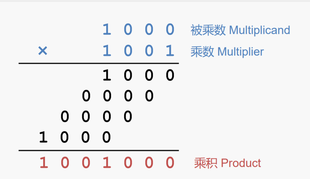
二进制乘法与我们熟悉的十进制乘法类似,其原理都是被乘数与乘数的每一位按位相乘并进行移位,其原理示意图如下图所示:

据此,我们自然可以想到,先将被乘数进行扩位到乘积的位宽,同时被乘数和乘数进行移位(被乘数左移,乘数右移),通过判断乘数最低位进而累加被乘数,从而可以得到最终的乘积结果。由于乘积的宽度不会大于被乘数和乘数位宽之和,所以就首先将被乘数扩位到两者之和的位宽即可。再向前一步,由于移位累加需要的周期数至少是乘数的位宽,所以我们可以采用流水线的方式,将每一步累加的结果都保存下来,进而给下次的乘法腾出计算空间,这样可以提升乘法器运行的效率。
3. 代码
所有程序编辑平台为vscode,仿真平台为ubuntu系统中的vcs工具,分别包括源文件mult_low.v ,mult_cell.v,mult_pipeline.v,仿真文件mult_low_tb.v,mult_pipeline_tb.v,路径名列表文件mult_low.f,mult_pipeline.f和``makefile`文件,其中源文件和仿真文件的原始来源是 6.7 Verilog流水线。文件具体内容如下
源文件 mult_low.v
module mult_low #(
    parameter N = 4,
    parameter M = 4 ) (

    input               clk,
    input               rstn,
    input               data_rdy,   // 数据输入使能
    input  [N-1:0]      mult1,
    input  [M-1:0]      mult2,

    output              res_rdy,   // 数据输出使能
    output [N+M-1:0]    res
);

    // 下面的always过程块很重要,会让cnt=0保持两个时钟周期,从而让计算不出错
    reg [31:0] cnt;
    wire [31:0]          cnt_temp = (cnt == M)? 'b0 : cnt + 1'b1 ;
    always @(posedge clk or negedge rstn) begin
        if (!rstn) begin
            cnt    <= 'b0 ;
        end
        else if (data_rdy) begin    //数据使能时开始计数
            cnt    <= cnt_temp ;
        end
        else if (cnt != 0 ) begin  //防止输入使能端持续时间过短
            cnt    <= cnt_temp ;
        end
        else begin
            cnt    <= 'b0 ;
        end
    end

    reg [M-1:0]     mult2_shift;
    reg [N+M-1:0]   mult1_shift;
    reg [N+M-1:0]   mult1_acc;
    always @(posedge clk or negedge rstn) begin
        if (!rstn) begin
            mult2_shift <= 'b0;
            mult1_shift <= 'b0;
            mult1_acc   <= 'b0;
        end

        // 初始化的过程,所以在前面添加的是0
        else if (data_rdy && cnt=='b0) begin
            mult1_shift <= , mult1} << 1;
            mult2_shift <= mult2 >> 1;
            mult1_acc   <= mult2[0] ? , mult1} : 'b0;
        end

        // 就是移位累加的过程
        else if (cnt != M) begin
            mult1_shift <= mult1_shift << 1;
            mult2_shift <= mult2_shift >> 1;
            mult1_acc   <= mult2_shift[0] ? mult1_acc + mult1_shift : mult1_acc;
        end

        else begin
            mult2_shift <= 'b0;
            mult1_shift <= 'b0;
            mult1_acc   <= 'b0;
        end

    end

    reg [N+M-1:0]   res_r;
    reg             res_rdy_r;
    always @(posedge clk or negedge rstn) begin
        if (!rstn) begin
            res_r       <= 'b0;
            res_rdy_r   <= 'b0;
        end

        else if (cnt == M) begin
            res_r       <= mult1_acc;
            res_rdy_r   <= 1'b1;
        end

        else begin
            res_r       <= 'b0;
            res_rdy_r   <= 'b0;
        end
    end

    assign res        = res_r;
    assign res_rdy    = res_rdy_r;
endmodule
仿真文件 mult_low_tb.v
module mult_low_tb;
    parameter N = 8;
    parameter M = 4;

    reg clk, rstn;
    always begin
        clk = 0; #5;
        clk = 1; #5;
    end

    initial begin
        rstn = 1'b0;
        #8 rstn = 1'b1;
    end

    reg [N-1:0]         mult1;
    reg [M-1:0]         mult2;
    reg                 data_rdy;
    wire [N+M-1:0]      res;
    wire                res_rdy;

    mult_low #(.N(N), .M(M)) inst1 (
            .clk        (clk),
            .rstn       (rstn),
            .data_rdy   (data_rdy),
            .mult1      (mult1),
            .mult2      (mult2),
            .res        (res),
            .res_rdy    (res_rdy)
    );

    // 使用任务周期激励
    task mult_data_in;
        input [M+N-1:0] mult1_task, mult2_task;
        wait(!mult_low_tb.inst1.res_rdy);
        @(negedge clk);
        data_rdy = 1'b1;
        mult1 = mult1_task;
        mult2 = mult2_task;
        @(negedge clk);
        data_rdy = 1'b0;
        wait(mult_low_tb.inst1.res_rdy);
    endtask

    initial begin
        mult_data_in(25, 5);
        mult_data_in(16, 10);
        mult_data_in(10, 4);
        mult_data_in(15, 7);
        mult_data_in(215, 9);
    end

    initial begin
        #1000 $finish;
    end

    wire [3:0] cnt;
    assign cnt = inst1.cnt;


endmodule
路径列表文件 mult_low.f
./mult_low.v
./mult_low_tb.v
源文件 mult_cell.v
module mult_cell #(
    parameter N = 4,
    parameter M = 4
)
(
    input                   clk,
    input                   rstn,
    input                   en,
    input   [M+N-1:0]       mult1,
    input   [M-1:0]         mult2,
    input   [M+N-1:0]       mult1_acci,

    output reg [M+N-1:0]    mult1_o,
    output reg [M-1:0]      mult2_shift,
    output reg [M+N-1:0]    mult1_acco,
    output reg              rdy
);

    always @(posedge clk or negedge rstn) begin
        if (!rstn) begin
            rdy         <= 'b0;
            mult1_o     <= 'b0;
            mult1_acco  <= 'b0;
            mult2_shift <= 'b0;
        end

        else if (en) begin
            rdy         <= 'b1;
            mult2_shift <= mult2 >> 1;
            mult1_o     <= mult1 << 1;

            if (mult2[0]) begin
                mult1_acco <= mult1_acci + mult1;
            end

            else begin
                mult1_acco <= mult1_acci;
            end
        end

        else begin
            rdy             <= 'b0;
            mult1_o         <= 'b0;
            mult1_acco      <= 'b0;
            mult2_shift     <= 'b0;
        end
    end

endmodule
源文件 mult_pipeline.v
module mult_pipeline #(
    parameter N = 4,
    parameter M = 4
)(
    input               clk,
    input               rstn,
    input               data_rdy,
    input   [N-1:0]     mult1,
    input   [M-1:0]     mult2,

    output              res_rdy,
    output  [N+M-1:0]   res
);

    wire [N+M-1:0]  mult1_t         [M-1:0];
    wire [M-1:0]    mult2_t         [M-1:0];
    wire [N+M-1:0]  mult1_acc_t     [M-1:0];
    wire [M-1:0]    rdy_t;

    // 初始化的数据和后面例化数据不同,不可以用generate例化
    mult_cell #(.N(N), .M(M)) inst0(
            .clk            (clk),
            .rstn           (rstn),
            .en             (data_rdy),
            .mult1          (, mult1}),
            .mult2          (mult2),
            .mult1_acci     ({(N+M){1'b0}}),

            .mult1_acco     (mult1_acc_t[0]),
            .mult2_shift    (mult2_t[0]),
            .mult1_o        (mult1_t[0]),
            .rdy            (rdy_t[0])
    );

    genvar  i;
    generate
        for (i=1; i<=M-1; i=i+1) begin:mult_stepx
            mult_cell #(.N(N), .M(M)) inst (
                .clk            (clk),
                .rstn           (rstn),
                .en             (rdy_t[i-1]),
                .mult1          (mult1_t[i-1]),
                .mult2          (mult2_t[i-1]),
                .mult1_acci     (mult1_acc_t[i-1]),

                .mult1_acco     (mult1_acc_t[i]),
                .mult1_o        (mult1_t[i]),
                .mult2_shift    (mult2_t[i]),
                .rdy            (rdy_t[i])
            );
        end
    endgenerate

    assign res_rdy      = rdy_t[M-1];
    assign res          = mult1_acc_t[M-1];
endmodule
路径名列表文件 mult_pipeline.f
./mult_cell.v
./mult_pipeline.v
./mult_pipeline_tb.v
仿真文件 mult_pipeline_tb.v
module mult_low_tb;
    parameter N = 8;
    parameter M = 4;

    reg clk, rstn;
    always begin
        clk = 0; #5;
        clk = 1; #5;
    end

    initial begin
        rstn = 1'b0;
        #8 rstn = 1'b1;
    end


    reg                 data_rdy ;
    reg [N-1:0]         mult1 ;
    reg [M-1:0]         mult2 ;
    wire                res_rdy ;
    wire [N+M-1:0]      res ;

    //driver
    initial begin
        #55 ;
        @(negedge clk ) ;
        data_rdy  = 1'b1 ;
        mult1  = 25;      mult2      = 5;
        #10 ;      mult1  = 16;      mult2      = 10;
        #10 ;      mult1  = 10;      mult2      = 4;
        #10 ;      mult1  = 15;      mult2      = 7;
        mult2      = 7;   repeat(32)    #10   mult1   = mult1 + 1 ;
        mult2      = 1;   repeat(32)    #10   mult1   = mult1 + 1 ;
        mult2      = 15;  repeat(32)    #10   mult1   = mult1 + 1 ;
        mult2      = 3;   repeat(32)    #10   mult1   = mult1 + 1 ;
        mult2      = 11;  repeat(32)    #10   mult1   = mult1 + 1 ;
        mult2      = 4;   repeat(32)    #10   mult1   = mult1 + 1 ;
        mult2      = 9;   repeat(32)    #10   mult1   = mult1 + 1 ;
    end

    //对输入数据进行移位,方便后续校验
    reg  [N-1:0]   mult1_ref [M-1:0];
    reg  [M-1:0]   mult2_ref [M-1:0];
    always @(posedge clk) begin
        mult1_ref[0] <= mult1 ;
        mult2_ref[0] <= mult2 ;
    end

    genvar         i ;
    generate
        for(i=1; i<=M-1; i=i+1) begin
            always @(posedge clk) begin
            mult1_ref[i] <= mult1_ref[i-1];
            mult2_ref[i] <= mult2_ref[i-1];
            end
        end
    endgenerate

    //自校验
    reg  error_flag ;
    always @(posedge clk) begin
        # 1 ;
        if (mult1_ref[M-1] * mult2_ref[M-1] != res && res_rdy) begin
            error_flag <= 1'b1 ;
        end
        else begin
            error_flag <= 1'b0 ;
        end
    end

    //module instantiation
    mult_pipeline #(.N(N), .M(M)) inst1
     (
      .clk              (clk),
      .rstn             (rstn),
      .data_rdy         (data_rdy),
      .mult1            (mult1),
      .mult2            (mult2),
      .res_rdy          (res_rdy),
      .res              (res));

    initial begin
        #10000 $finish;
    end

endmodule
makefile文件
.PHONY: com_low sim_low com_pipeline sim_pipeline clean

VCS = vcs 	-sverilog +v2k -timescale=1ns/1ns \
			-debug_all

com_low:
		${VCS} -f mult_low.f -o simv_low

com_pipeline:
		${VCS} -f mult_pipeline.f -o simv_pipeline

sim_low:
		./simv_low -gui

sim_pipeline:
		./simv_pipeline -gui

clean:
		rm -rf ./csrc ./DVEfiles *.daidir *.log simv* *.key *.vpd
程序中有一些需要注意的点:
1. 在源文件mult_low.v中第一个always块很重要,会让cnt==0时保持两个时钟周期,这样计算才会正确;
2. 源文件mult_pipeline.v中定义的二维数组使用的是wire,因为既要当输入又要当输出;
3. 源文件mult_pipeline.v中初始化例化不可以放在generate中,因为输出信号不同;
4. 源文件mult_pipeline.v中初始化例化和generate中的例化可以看出,前一阶段输出是下一阶段输入,并被保存起来,符合流水线定义;
5. 路径名列表文件mult_pipeline.f中需要有mult_cell.v的路径,否则仿真的时候找不到会出错;
4. 仿真结果
下图是使用vcs软件仿真不具有流水线功能的乘法器得到的波形图

下图是使用vcs软件仿真具有流水线功能的乘法器得到的波形图

我们可以明显看到,使用了流水线结构之后,在一定时钟周期之后,每个时钟周期都会输出一个结果,而没有采用流水线结构的乘法器,每得到一个结果都必须要等待一定的时钟周期,流水线结构对于提升计算效率的确有很大帮助。与此同时,流水线结构也消耗了大量的硬件存储资源(包括二维存储器),这是一个典型的用资源换效率的设计思路。
文档信息
- 本文作者:Polaris
- 本文链接:https://polaris-chn.github.io/2022/04/10/Verilog-practice-2/
- 版权声明:自由转载-非商用-非衍生-保持署名(创意共享3.0许可证)
